Purpose
In this window, the thermal conditions of the oven and the heat transfer dynamics must be defined. These parameters determine how and how quickly the polymer will melt and form the part wall.
1. Temperature Configuration
- Maximum Oven Temperature (Tmax)
- This is the oven setpoint temperature.
Technical Note: This value should represent the actual average temperature inside the oven. Since machine panel settings often differ from the internal reality, use the real measured value for simulation accuracy. - Room Temperature
- The ambient temperature of the production plant.
- Initial Mould Temperature
- The temperature of the mould at the beginning of the cycle.
Critical Rule: This field should never be left at 0 °C. It must always be set to a real value and cannot be lower than the room temperature.
Important: If the mould is already in production (continuous cycle), enter the actual temperature of the mould before it enters the oven to avoid errors in calculating the melting time.
2. Heating Ramp (Optional)
The Heating Ramp allows you to model the thermal inertia of the oven instead of assuming an instantaneous temperature jump.
- Usage: Define the starting air temperature when the arm enters and the time it takes to reach Tmax.
- Default Behavior: If the ramp is not activated, the solver automatically assumes an initial temperature of 50 °C and a duration of 3 minutes to reach the set temperature.
3. Airflow Dynamics (Air Flow Type)
This is the most influential parameter for convective heat transfer. It determines the general convective coefficient within the oven.
- No Airflow (Still Air): Static air conditions.
- Fan-driven: Airflow induced by fans (5 intensity levels available).
- Blower-driven: High-power forced airflow (5 intensity levels available).
While the flow type sets the base coefficient, the part geometry will automatically determine the actual convective coefficient on each specific zone of the surface.
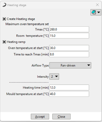 Figure 1: Heating Stage parameters window configuration.
4. Oven Calibration (Intensity Adjustment)
To determine the real heat transfer value of your specific machine, follow this professional calibration procedure:
- Simulate a known part for which you already have real-world process results.
- Compare the time it takes for all the material to adhere (found in the .log file or XY process graphs) with the actual time from your process.
- If the simulation is slower than reality, increase the airflow intensity; if it is faster, decrease it.