Purpose
This function allows identifying areas on the mould where thermal insulation has been applied (such as fiberglass patches, Teflon, or other insulators) to reduce heat transfer. It is primarily used to prevent overheating in specific zones and, consequently, to avoid excessive polymer adhesion or to reduce thickness where it is not desired.
💡 Technical Recommendation: Also use this tool if you consider that any area of the mold is obstructed from air flow due to the proximity of another mold. Adjust the insulation value accordingly to simulate this thermal "shadow" effect.
1. Insulation Effectiveness
The core parameter is the Effectiveness of insulation [%]. This value scales the heat transfer coefficient to simulate the thermal resistance of the material applied.
A value of 100% represents a perfect theoretical insulation (total heat block). The user should input a percentage that represents the real-world thermal resistance provided by the insulation patch.
2. Geometry Identification and Assignment
As explained in previous sections, for the software to apply these properties, the target area must be a delimited surface within the model.
- Native CAD: Ideally, the CAD file should already have these surfaces delimited and identified before importing, ensuring they are easily selectable with the exact shape of the insulation patch.
- SIMOULDING Tool: If the surfaces are not delimited in the original file, the user must use the SIMOULDING geometry tool to partition the mould faces into identifiable zones.
To assign the data: Define a name, enter the effectiveness (min. 5%), click Assign, and select the delimited surfaces in the 3D model.
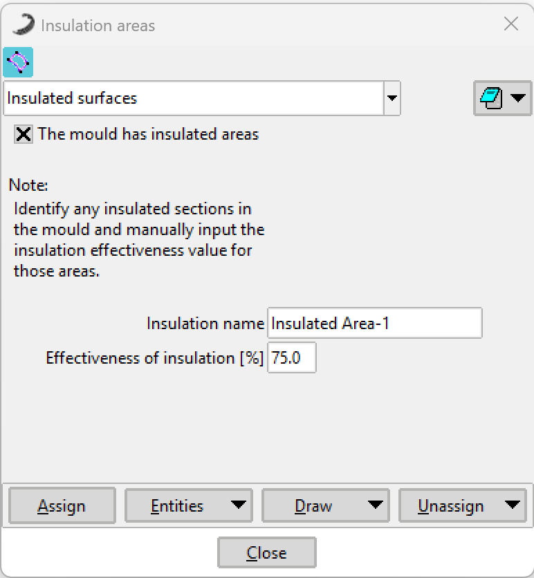 Figure 1: Insulation Areas configuration window.
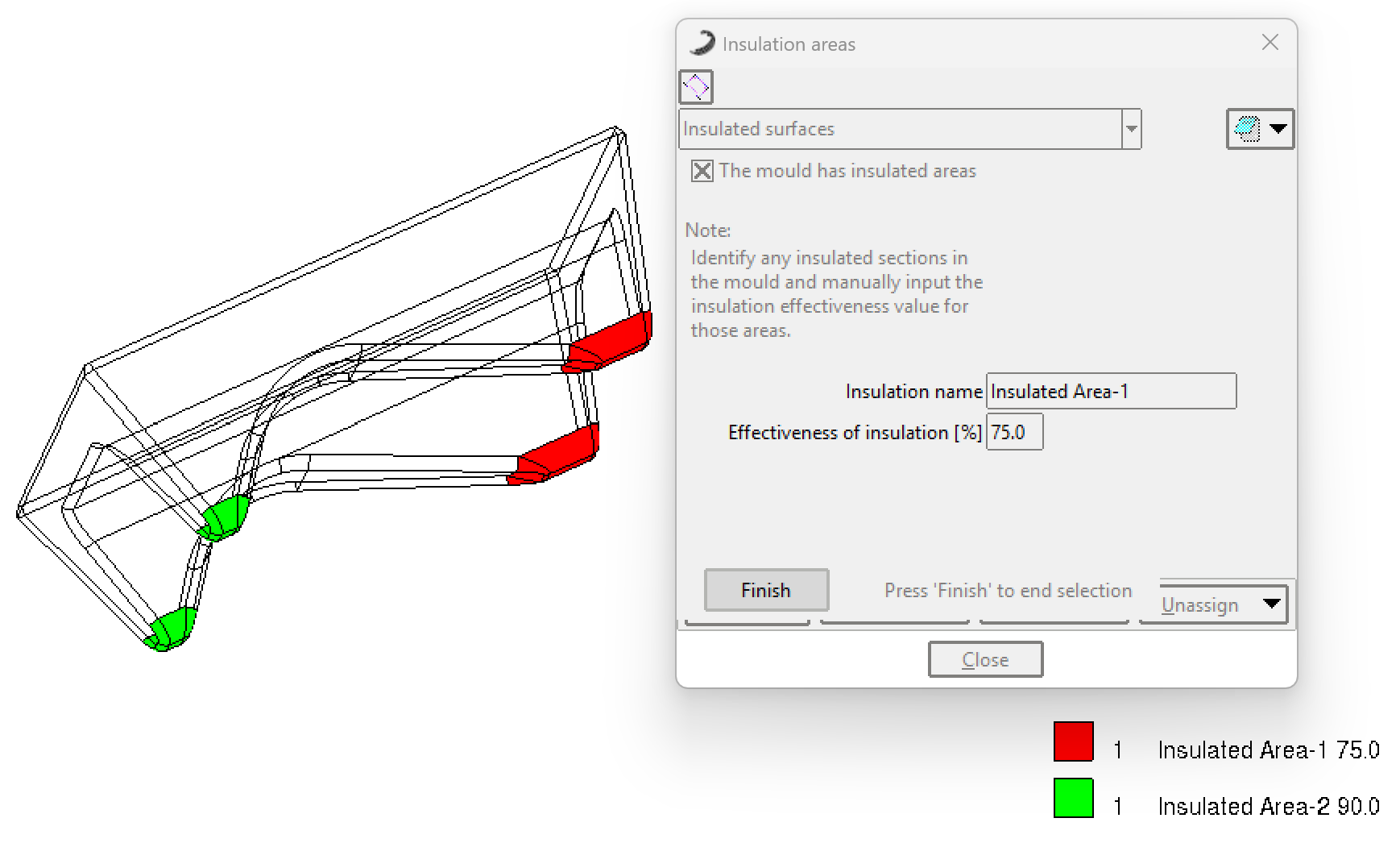 Figure 2: Example of assigning delimited surfaces for thermal insulation.