Purpose
In this window, the data related to the type of machine and rotation speeds must be entered. These parameters determine the kinematic behavior of the mould and, consequently, the polymer distribution during the simulation.
1. Motion Configuration
SIMOULDING offers the option to choose between two main movement types:
- Biaxial 360°: Continuous rotation on both axes. You must enter the RPM for the Main Arm and the Platters.
- Rock and Roll: Rocking motion combined with secondary axis rotation. This requires defining the Rocking Angle and the Dwell Time (waiting time at both ends).
Reverse Rotation: Available for both modes. In Biaxial, it affects both axes; in Rock and Roll, it only applies to the secondary axis (platters).
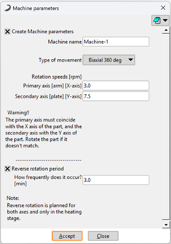 Figure 1: Machine Parameters window in Biaxial 360° mode.
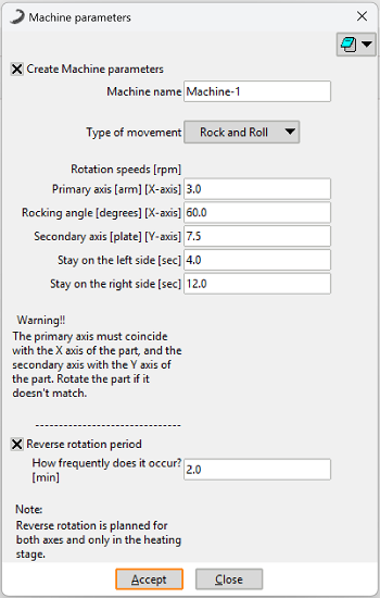 Figure 2: Machine Parameters window in Rock and Roll mode.
2. Axis Convention & Alignment (CRITICAL)
- X Axis: Aligned with the Main Axis (Arm).
- Y Axis: Aligned with the Secondary Axis (Platters/Spider).
The exact final position on the spider, the distance relative to the main arm, and the selection of the arm type will be configured later in the Mould Position section. However, the base orientation must be correct at this stage.
3. Correcting Orientation (Utilities > Move)
If the imported CAD does not match the described convention, you must rotate the part using the Move tool:
- Go to the menu: Utilities > Move.
- In the window, select Rotation and All types.
- Define the rotation axis: You must enter two points to define the axis line.
Example: To rotate around the X-axis, enter 0, 0, 0 for the first point and 10, 0, 0 for the second point. - Select the entire part and press ESC to confirm.
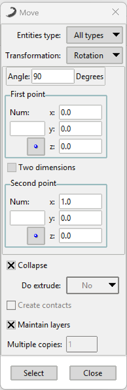 Figure 3: Configuring the rotation axis in the Utilities > Move menu.