Purpose
Once the geometry is defined, the next step is to discretize the volume into volume elements. These elements form the mathematical foundation that SIMOULDING uses to calculate material distribution and thermal variables.
1. Mesh Consistency
It is crucial that the Element Size is consistent with the Simulation Mode selected in section 2.2. Define Project:
- Draft Mode: Requires coarser meshes for higher speed.
- Balanced Mode: Intermediate resolution.
- High Quality Mode: Requires refined meshes to capture precise thermal gradients.
Log Analysis: The log file is written once the simulation starts. It is highly recommended to check it at the beginning of the calculation. The software performs an automated compatibility analysis between the Project Mode and the generated Mesh. Any technical inconsistency will be reported there to allow for adjustments.
2. Technical Requirements and Workflow
The workflow adapts according to the available input data:
- Volume Requirement
- To generate a mesh, a closed volume must exist. If no volume is detected, the mesh generation will fail, and the software will issue a warning.
- Direct Mesh Import (Volume Elements)
- If a mesh of volume elements (4-node tetrahedrons) is imported, no CAD geometry is required. All assignments (insulation, venturis, etc.) are performed directly on the mesh elements. This is a fully valid standalone workflow.
- Surface Mesh Import (Triangles)
- If a triangle mesh is imported, it must be converted using the following SIMOULDING tools:
1. Create surface from mesh (Utilities -> Create surface from mesh)
2. Create volume from surface (Utilities -> Create volume from surface)
3. Finally, Generate the volume mesh.
2. Create volume from surface (Utilities -> Create volume from surface)
3. Finally, Generate the volume mesh.
3. Supported Formats
- .msh (SIMOULDING/GiD), .nas (NASTRAN), .inp (Abaqus), VTK, and STL (Stereolithography).
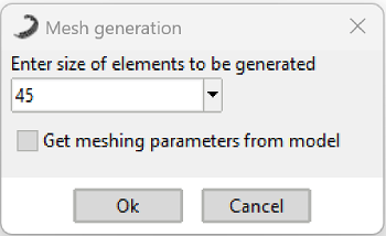 Figure 1: GiD Mesh generation dialog.
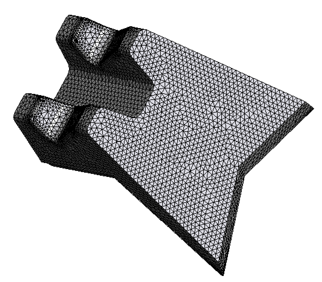 Figure 2: Representative volume mesh for simulation.