Purpose
In this section, the physical and mechanical properties of the mould are defined. These data are crucial for the solver to calculate thermal inertia and the heat transfer to the material.
1. Mould Material
Select the material of your mould to load its specific thermal properties (conductivity and specific heat):
- Aluminum casting / Aluminum alloy
- Sheet steel / Sheet stainless steel
2. Wall Thickness
Enter the nominal wall thickness of the mould in millimeters.
Note: If the mould has areas with significantly different thicknesses, these must be defined later in the Special Thicknesses section.
Thickness Constraints: The solver monitors thickness ranges. Values slightly out of range trigger a Warning in the Log, while extreme values will Abort the simulation to prevent errors.
3. Vents Configuration
- Vents quantity
- Total number of vent pipes installed in the mould.
- Vents diameter (mm)
- Internal diameter of the vent pipes. If no vent is present, enter 0.
Internal Pressure & Structural Risk: Entering a diameter of "0" will generate a critical warning.
- Heating Stage: Internal pressure increases, putting the structural integrity of the mould at risk.
- Cooling Stage: Negative pressure (vacuum) may occur, affecting part quality by causing excessive warpage.
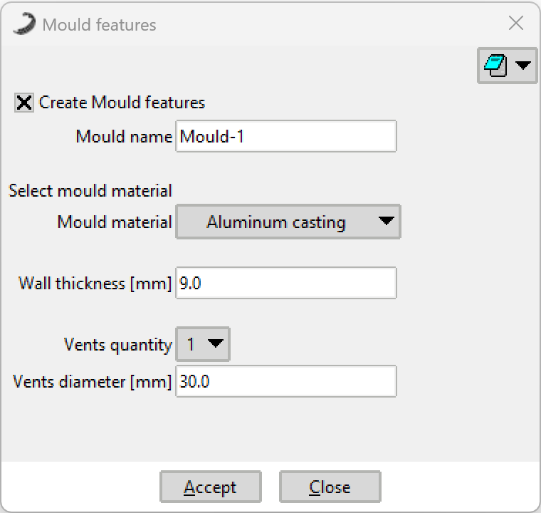 Figure 1: Mould Features configuration window.