Purpose
The Part Features section defines the material loading criterion for the simulation. In this step, you establish whether the calculation will be based on a desired part thickness or a known shot weight.
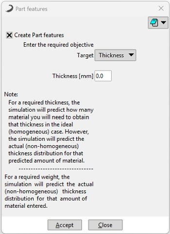 Figure 1: Part Features dialog window.
Configuration Modes
You must select one of the following mutually exclusive modes to define the material input:

Enter the desired nominal thickness for the part. The software uses this value as an objective to calculate the total material mass (Shot Weight) required to achieve it.
Enter the exact amount of material (in kg) that will be loaded into the mould. The software uses this fixed mass to calculate how it distributes along the walls, resulting in the final thickness map of the part.
Technical Considerations
Polymers Interaction: The values defined here are combined with the density of the material selected in the next section (Polymers) for all volumetric calculations.
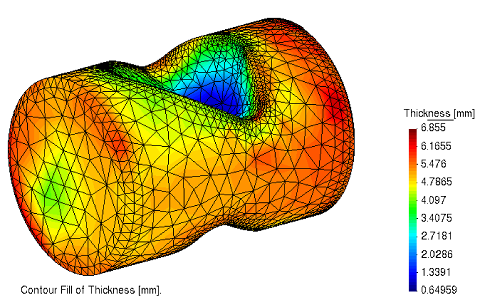 Figure 2: Example result showing actual thickness distribution (irregular walls), regardless of the input method.