Purpose
This function allows assigning specific thicknesses to certain areas of the mould that differ from the overall thickness defined in the Mould Features window. It is an essential tool for accurately modeling structural reinforcements, flanges, or variations inherent in cast aluminum moulds.
1. Geometry Identification
To assign a special thickness, the target area must be a delimited surface within the model.
If the imported geometry lacks a delimited surface for a specific zone, the user can use the SIMOULDING geometry tool to partition the mould faces. This allows creating new surfaces that are identifiable and selectable for assignment.
2. Assigning Data
Within the Special Thicknesses window, follow these steps:
- Surface name
- Define a descriptive name for the group (e.g., "3mm_Thickness_Zone").
- Surface thickness (mm)
- Enter the actual thickness value for that specific delimited area.
- Assign
- Click this button, then select the surfaces in the 3D view and press Enter to link them to the value.
The user can create multiple groups for different thickness values. Use the Draw button to visually verify which surfaces have been assigned to each group.
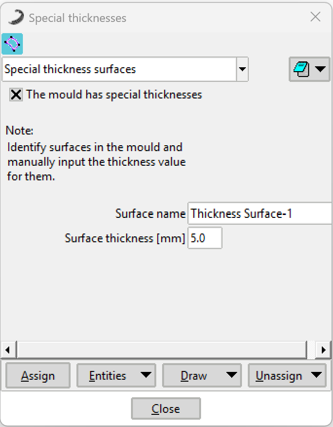 Figure 1: Special Thicknesses configuration window.
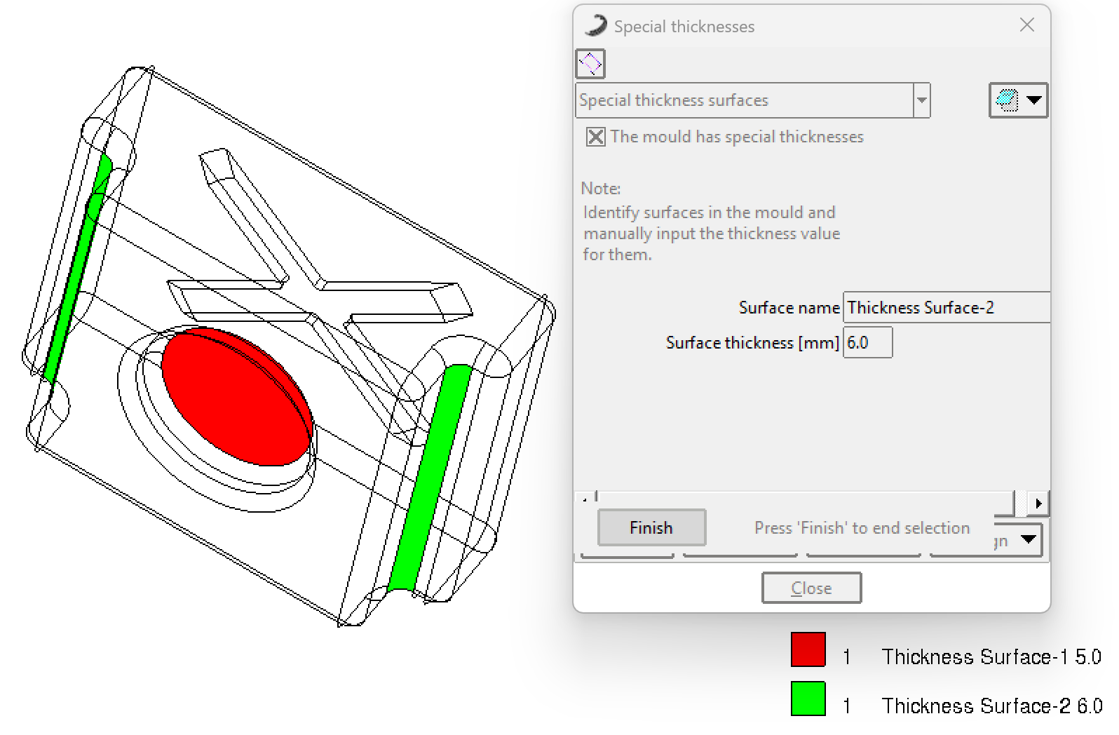 Figure 2: Example of assigning delimited surfaces in the 3D model.